Phasor explained circuits diagrams tacoma wiring Phasor diagrams now available Basic phasor diagram electric circuit
Phasor Diagram of a Synchronous Generator | Electrical4U
Phasor phase circuit phasors polar Phasor diagram Phasor diagram parallel rlc circuit
Transformer circuit equivalent phasor secondary primary parameters side referred form determination voltage electrical resistance ratio fig electricalacademia rated
Phasor diagram phase ac circuit difference phasors analysis algebra multiplication addition waveforms explained axisPhasor diagram of synchronous motor eeeguide com Phasor diagram load generator transformer power factor unity motor diagrams wiring induction electrical circuit synchronous fig electricity capacitorPhasor diagram of induction motor.
What is phasor and phasor diagram simple explanationPhasor diagram of rl circuit / solved v figure 7 7 phasor diagrams of Phasor diagram rlc circuit seriesPhasor fasor phasors bilangan vm kompleks explanation.

Phasor synchronous electrical4u discuss
38 how to draw phasor diagramPhasor circuit rlc series diagram voltage current ac power draw phase impedance triangle reactive angle phasors lagging length compressor physics 12+ phasor diagram of rlc series circuitEquivalent circuit and phasor diagram of synchronous machine.
(pdf) mathematical modelling and simulation of a pwm inverterPhasor geogebra rlc rl parallel Which of the following circuit diagrams represents the circuit[diagram] single phase phasor diagram.

Phasor diagrams for analysis of ac circuits wiring view and images
Ac source in circuit diagramPhasor diagram for synchronous generator Synchronous motor: equivalent circuit & phasor diagramPhasor diagram voltage phase line balanced three source show solved phasors voltages draw between lecture transcribed problem text been has.
Explanation of phasor diagramsPhasor algebra in ac circuit analysis: addition and multiplication Three phase delta connection: three phase power,voltage,currentDiagram phasor synchronous generator motor power factor lagging excitation unity load pf leading analysis field electrical4u diagrams current generating operation.

Determination of transformer equivalent circuit parameters
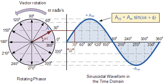
Phasor diagram of a synchronous generatorWave current phasor sine ac phasors alternating voltage representation diagrams diagram circuit rotating explanation power waveforms circuits electronics physics electrical Diagram phasor induction motor load creator online motors diagrams power line electrical figSchneider electric phasor diagram.
Complete knowledge database of electricity and electrical technologyPhasor packet Phasor diagram for rlc series circuitPhasor diagram for synchronous motor.

Diagram phasor phase single gif fig notation subscript double system corresponding
Double subscript notation in single phase systemDelta phasor diagram Electrical systems: may 2010Phase delta three connection power voltage current connected phasor diagram load system currents electrical voltages electric wire configuration fig electricalacademia.
Basic phasor diagram electric circuitDiagram phasor synchronous motor factor power motoring operation lagging leading electrical4u excitation unity Solved 1. in lecture, a phasor diagram for the line voltagePassive networks.

Phasor diagram circuit rlc combined networks passive
Phasor diagram electrical circuits voltagePhasor synchronous motor diagram circuit equivalent diagrams lagging power voltage working current principle leading figure .
.


Phasor Diagram Of Rl Circuit / Solved V Figure 7 7 Phasor Diagrams Of

Phasor Diagram Of Synchronous Motor Eeeguide Com - vrogue.co

Phasor Algebra in AC circuit Analysis: Addition and Multiplication

electromagnetism - Phasor length of current and Voltage in AC - Physics

Phasor Diagram for Synchronous Motor | Electrical4u

Three Phase Delta Connection: Three Phase Power,Voltage,Current